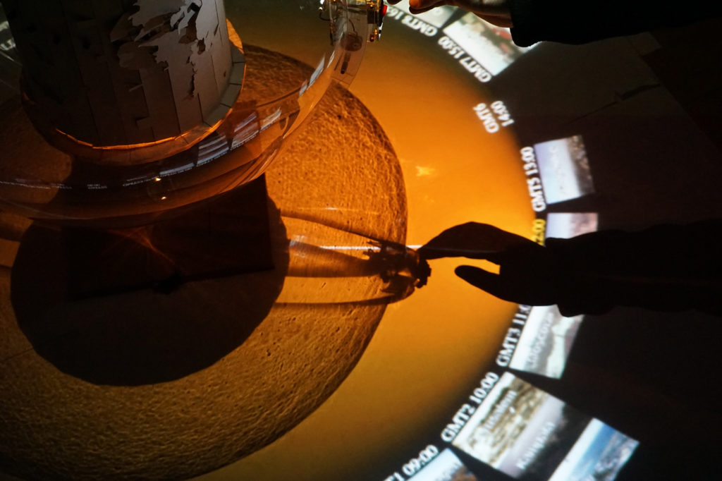
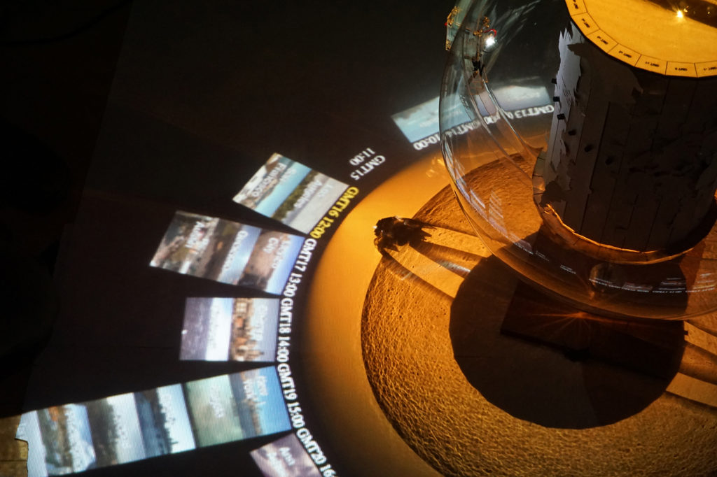
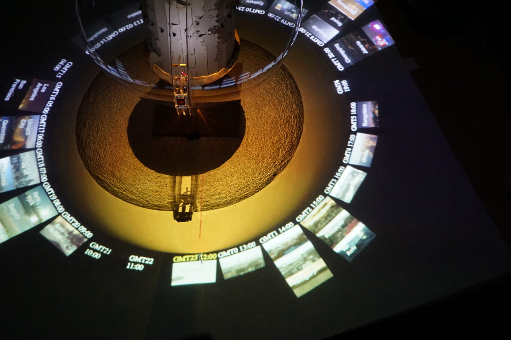
(Photos by Nicolas Peña-Escarpentier)
What's time? A project “Time” started from throwing simple questions about time and its standard - eventually evolving into the combination of physical piece and digital visualization about different time zones. The physical piece is consisted of two parts: inner cylinder that represents UTC Time Zone map, and outer sphere that is rotatable and contains light source. As the user rotates the outer sphere, and it creates movement in light. While the light is moving, the inner cylinder that has 24 light sensors for each longitude reacts to the changing brightness.
The physical piece will be installed on transparent and round table that I personally own, which approximately has 40” diameter and 30” height. People should be able to walk around the table and see the cylinder time zone map inside the sphere. The digital visualization will be projected from underneath the table; due to its transparency, the table is able to directly show the visualization on is top surface. In this way, people can view both physical and digital piece without being distracted.
When the light shifts from one time zone to another, the digital visualization reflects the movement as well by changing gallery of skylines. Those skylines are from survey towards ITP community regarding which cities they came from, and organized according to the longitude location.
All the coding parts can be found in my or Huiyi's GitHub repository.
Process:
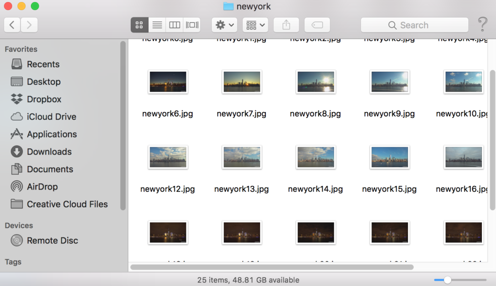
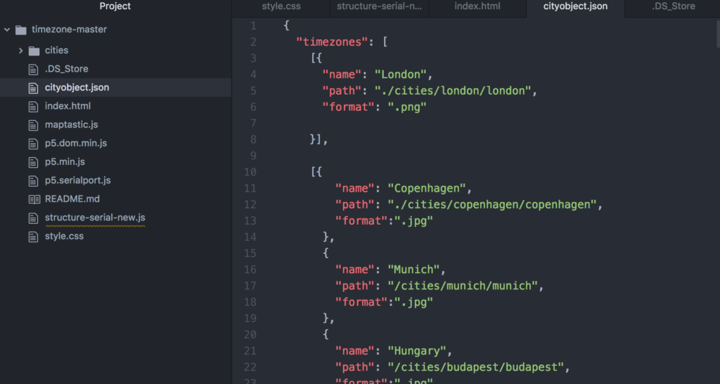
The skyline photos are are collected in a single folder and organized in each city with same 24 steps. The archive is called via .json file.


24 light sensors send array of numbers. During this process, Huiyi and I had to add black tubes around the sensors to block the ambient light. Usually when the light source is not close enough, the reading is under 10~15. When the light source is in front of the sensor, it gives value between 50~100. Using that, if there's enough difference between max and min, it will indicate max as 12:00PM.
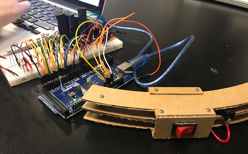
What happens if the difference between max and min is too small - such as, when the light is off because I put the switch on the light source without thinking everyone's going to press it? Well, it basically makes the whole sketch goes to "sleep." This won't and shouldn't happen in real life, but since our work is not literally showing the scientific information, we rather found it will be a good visual effect that wraps up the whole idea.
Second User Testing:
In order to give a general idea of how it functions, I brought the partially completed physical piece and the sketch that works with slider input. Although Huiyi and I were in the finishing stage at this point, the user testing was helpful to make small fixes. The most mainstream feedback I got was that it's hard to recognize the light location inside the sketch.

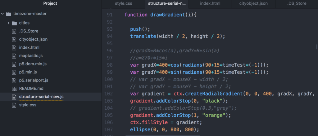
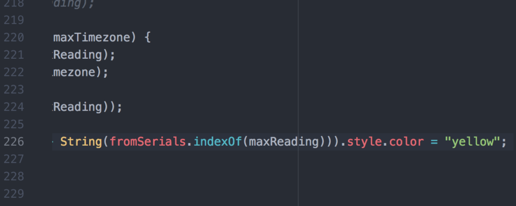
After the user testing, Huiyi and I realized the need of light indicator and initially built a white line that goes across the sketch and directs to the max input - which is the version I presented in the last ICM class. Then later it became a line along with orange gradient to make the light change more noticeable and dramatic. Furthermore, the text color for max input zone will be turn into yellow as well.
Results:
This is the second short video that contains some process and imagery of how it works. There will be more documentation and modification until the show.